
Contents
The capacity bottleneckPlanning for controlled demandCharging alongside household loadsTwo levels of allocationVerifying control performance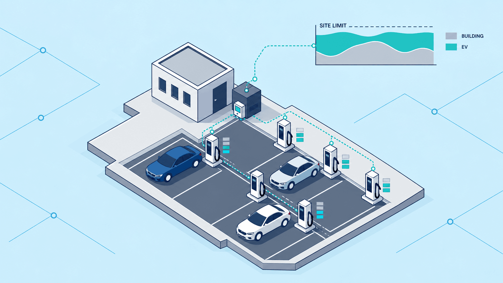
The capacity bottleneck
A parking facility may have room for six charging bays while its existing electrical supply can support only three chargers at their chosen maximum output. The owner can reduce the number installed, restrict their output, or seek a supply upgrade. Energy Saving Trust describes this trade-off in its guidance on fleet charging infrastructure.[2]
The useful distinction is between providing access to charging and supplying every vehicle at maximum power throughout its stay. Vehicles arrive with different energy needs and departure times. Managed charging uses that flexibility to share available capacity, with more power available to individual vehicles when fewer are charging.[2]
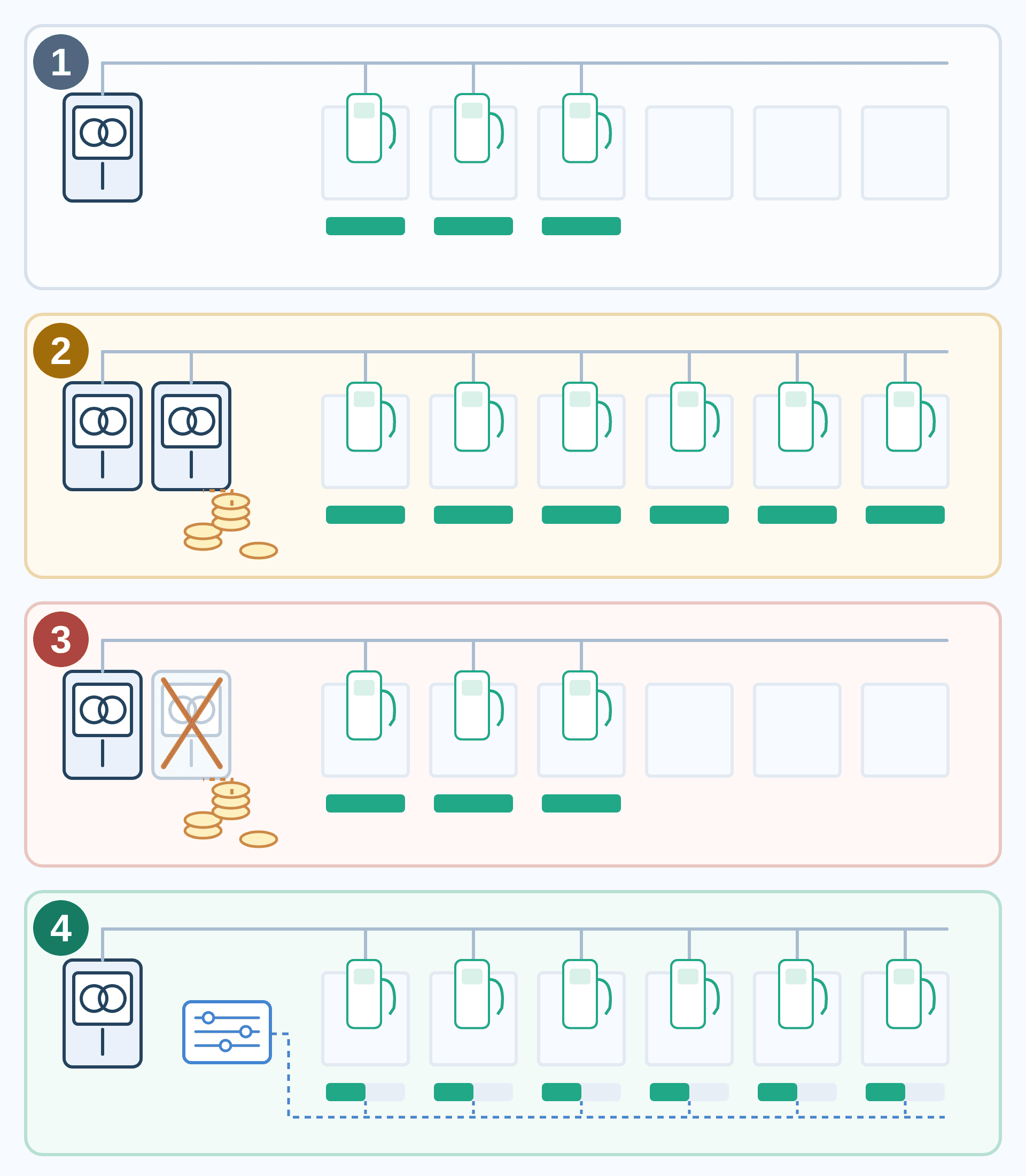
1 · Keep the supply, install three
Only some parking bays receive chargers, keeping their combined allowance within the existing capacity.
2 · Pay for an upgrade, install six
A larger supply provides room for six chargers with higher individual allowances.
3 · An upgrade is unavailable
Willingness to invest cannot secure additional supply capacity. The site remains limited to three chargers in this example.
4 · Share the supply, install six
A management system limits simultaneous demand and allocates the existing capacity across six chargers.
Coins indicate upgrade expenditure; the cross marks a blocked upgrade path. Dashed blue lines represent control, and green bars represent charging allowances. Counts are illustrative. Option 4 assumes controlled total demand and enough parking time to meet energy needs at lower charging rates.[2][5]
This is a practical problem for existing buildings. CSA Group’s 2019 research on electric vehicle energy management systems (EVEMS) identified the mismatch between established building capacity and new charging loads, together with the cost of upgrades, as a reason to develop these systems.[3]
Planning for controlled demand
An installation also needs a defensible basis for its load calculation. An expectation that vehicles will rarely charge together provides less certainty than a system that enforces a maximum simultaneous load. Ontario’s Electrical Safety Authority distinguishes charging without an energy management system (EMS) from EMS-controlled charging; its May 2025 bulletin allows the charging demand to be based on the maximum load permitted by the EMS.[4]
That distinction gives controlled demand a place in capacity planning. The applicable installation rules determine which arrangements qualify and how their loads are calculated. The engineering task is to establish a limit the system can reliably enforce.
Access to additional capacity can also affect when a site opens. A 2024 UK government review recorded operators’ concerns about completed chargepoints waiting to be energized, with no charging revenue during the wait. It recommended capacity ramping and curtailable connections where feasible. Managing demand can help a site operate within an available connection; connection procedures and construction constraints still need their own solutions.[5]
Charging alongside household loads
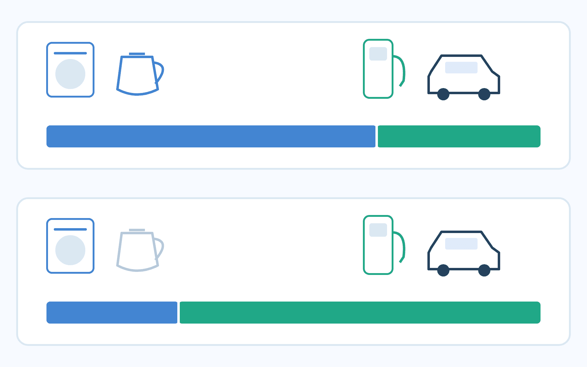
For an existing home without provision for EV charging, a charger joins appliances already drawing from a limited service. A new charging branch circuit from the distribution panel still shares that upstream capacity. Installing that circuit and obtaining a larger supply connection are separate decisions.
A permanently reduced charging limit can leave room for household demand. Its limitation appears when appliances switch off: the charger keeps the same low ceiling despite the released capacity. Dynamic control follows actual demand, reducing the charging allowance while other loads rise and restoring it when capacity becomes available.[1][2]
Sharing a service does not mean any household circuit can simply accept a charger. Ontario’s bulletin normally requires a separate charging branch circuit and provides a conditional route for a shared branch circuit when an EMS is installed.[4]
A low fixed limit can be an economical choice if it already meets daily charging needs. Dynamic allocation is more useful when a household’s busy periods constrain charging but its quieter periods offer capacity that a fixed limit leaves unused.
Two levels of allocation
A useful way to understand the control loop is to follow the information: metering reports site demand, a controller determines the available charging allowance, and the charging equipment applies the resulting current or power limits. Further measurements inform subsequent adjustments. This is a practical synthesis of the monitoring and control functions described in smart charge management guidance.[6]
Two allocations change. First, the site’s other loads determine how much capacity is available to charging as a whole. Second, that allowance is distributed among vehicles. When a vehicle departs, finishes charging or reduces its demand, capacity can be reassigned to others, subject to what each vehicle and charger can accept. Equal sharing and priority-based allocation are possible strategies; Figure 3 illustrates equal sharing.[1][7]
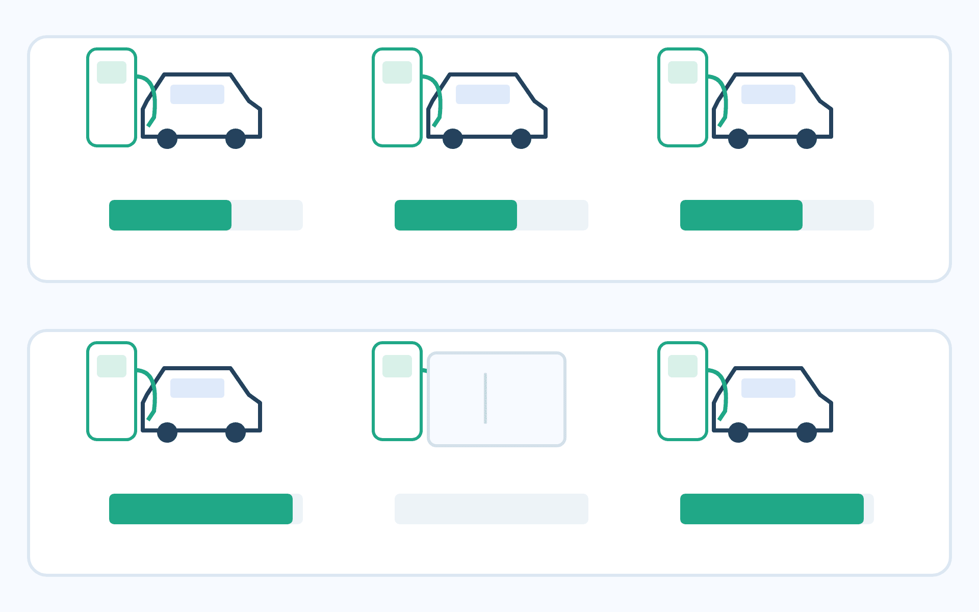
Static load management can also redistribute capacity among chargers. In the terminology used by Energy Saving Trust, it retains a fixed total charging allowance. Dynamic management additionally changes that allowance in response to other site loads. A changing output at one charger alone does not establish that the wider site demand is being monitored.[1]
Verifying control performance
A control system needs repeatable verification. CSA/ANSI C22.2 No. 343:25, Electric vehicle energy management systems, addresses functional safety control. Its public contents separately identify load management, Class B response time, current monitoring, communication-loss monitoring and protection against faults.[9][10]
The following observations explain what those topics mean in operation. They are reading aids; acceptance limits, system classifications and test conditions come from the applicable clauses.
| Verification topic | Observable evidence |
|---|---|
| Load management (4.2.1) | Compare configured limits with controlled-load traces as other loads increase or vehicles connect. |
| Class B response time (4.2.2) | Record response duration for the applicable classification and prescribed test conditions, then compare it with the relevant time requirement. |
| Current monitoring (4.2.3) | Compare monitoring readings with reference measurements to assess whether sensing supports correct load control. |
| Communication-loss monitoring (4.3.2) | Record loss detection, control actions and actual load during an interruption. |
| Fault protection for functional safety (4.6) | Record the behavior of safety-related control and the resulting load during relevant fault tests. |
For example, household load traces and charging actions can be observed together when an appliance starts. A communication interruption requires observation of the resulting operating state. Technical Safety BC’s EVEMS bulletin calls for verification of correct operation and a safe state, with loading constraints applying to the relevant branch circuits, feeders and service.[8]
First published in 2025 as both a Canadian and an American National Standard, CSA 343 covers EVEMS products, matched subassemblies and associated software. DLB describes an allocation function; EVEMS identifies a system that controls charging loads. Providing that function alone does not establish conformity of the complete system.[9]
Energy delivery remains a separate operating outcome. Measure how much energy vehicles receive during their agreed parking periods and identify unmet needs. Reliable load control makes capacity sharing possible; whether that sharing meets the intended charging service depends on available capacity, dwell time and allocation policy.
References
- [1] Load management — Energy Saving Trust; Undated webpage; Static / Dynamic load management
- [2] Charging profiles — Energy Saving Trust; Undated webpage; Sockets per vehicle
- [3] Electric Vehicle Energy Management Systems — CSA Group Research; May 2019; Executive Summary
- [4] Bulletin 86-1-7: Electric vehicle charging systems — Electrical Safety Authority, Ontario; May 2025; pages 1–2: EMS, branch circuits and load calculations
- [5] Improving the grid connection process for electric vehicle charging infrastructure — UK Office for Zero Emission Vehicles; 24 December 2024; Action area 1 and Action 2.7
- [6] Smart Charge Management Implementation for Federal Fleets — US Department of Energy / FEMP; Undated webpage; monitoring, control and data requirements
- [7] Principles of load management — Energy Saving Trust; Undated webpage; allocation as the number of vehicles changes
- [8] Electric Vehicle Supply Equipment (EVSE) and Electric Vehicle Energy Management Systems (EVEMS) — Technical Safety BC; 4 March 2025, Revision 3; safe states, acceptance and load constraints
- [9] CSA/ANSI C22.2 No. 343:25 — Electric vehicle energy management systems — CSA Group; public preface and scope hosted by ANSI; First edition, 2025; public preface and scope
- [10] CSA/ANSI C22.2 No. 343:25 — Contents — CSA Group; authorized preview hosted by Accuris; June 2025; contents page 1, clauses 4.2, 4.3 and 4.6