
Contents
From local control to shared rulesPutting rules into softwareBringing shared outcomes within scopeOverall coordination and local controlUpdating plans as conditions changeBroader scope and deeper decisions
In 1964, Cornell University installed a central chilled-water system to cool campus buildings, together with a manual monitoring system. Over the following decade, more building equipment was connected. Operators at the cooling plant used the system to monitor and control the on/off status of hundreds of fans and pumps across more than ten buildings.[1]
People were already organizing this equipment before computers joined the system: deciding where cooling was needed, which equipment should run and how to respond when conditions changed. Computers, software and controllers gradually took on parts of that work. Understanding an energy management system begins with how these responsibilities arose and how they came to be assigned to a system.
From local control to shared rules
Power systems of the same period already showed a distinction between equipment control and decisions for the system as a whole. When utility engineer Tomas E. Dy Liacco published his paper on reliability control in 1967, devices such as governors, voltage regulators and protective relays were already in use. Larger generating units, extra-high-voltage transmission and expanding interconnections made timely decisions across the power system increasingly complex.[2]
A generator can adjust its own output to a setpoint. The grid must also coordinate several generating units to meet demand and determine how equipment should respond when a line or generating unit goes out of service. The paper considered preventive action, emergency response and restoration separately, bringing together information systems, automatic control and human judgment. Different operating states called for different objectives and responses.[2]
These responsibilities help explain management: within a defined scope, establish operating rules for a shared objective, have the relevant participants act on them, and review and adjust the results. Rules specify acceptable operation, conditions that must be maintained, priorities when requirements conflict and who has authority to decide. An individual action puts those rules into effect under the conditions at hand.
Campus cooling and grid operation serve different purposes, but both depend on how several participants work together. Management therefore requires a view of the relevant system, a shared basis for decisions and a way to turn overall requirements into actions that each participant can carry out.
Putting rules into software
By the 1970s, energy costs were drawing more attention to building operating rules. In its account of this period, the US National Research Council identified the oil crisis, rising energy prices and building owners’ efforts to control operating costs as factors behind the development of building energy control technology.[3]
Equipment schedules and conditions in unoccupied spaces became opportunities to change how buildings operated. Assigning these tasks to software required explicit relationships between times, conditions and actions. The system also needed site data to determine whether the conditions in a rule had been met.[4][5]
Cornell added an IBM System/7 minicomputer to its manual monitoring system in 1975. A further upgrade in 1977 allowed the system to read temperature, pressure and flow information, and enabled university staff to write applications. In 1984, Cornell began installing direct digital control systems, giving digital controllers a role in operating building equipment.[1]
In this division of work, people define service requirements, operating objectives and the permitted scope of adjustment. Software records conditions, checks rules and prompts or carries out actions. People can establish the rules while the system handles execution and feedback; computing capability can also support the selection of operating plans. How much decision-making authority is delegated must be specified in the system’s design and configuration.[5][6]
Bringing shared outcomes within scope
The scope of a rule determines the information a system needs. In 1984, the US National Bureau of Standards already identified demand limiting as a common building energy management and control strategy. Under the relevant tariffs, the quantity to be limited is the highest average power over a demand measurement interval within the billing period. Meeting that objective requires considering the consumption of several devices together.[4]
A device’s temperature or on/off control addresses the local conditions it serves. Limiting demand for an entire building also requires knowing total consumption, which loads may be adjusted and their order of priority. The overall limit is then translated into operating plans for individual devices at different times.[4]
In a 2005 discussion of control for multiple chillers, the US Pacific Northwest National Laboratory also emphasized considering pumps, cooling towers and equipment performance at different loads. The energy consumption of the cooling plant depends on the combination in which its equipment operates.[5]
Management scope must be implemented through identifiable objects, accessible data and executable actions. Equipment interfaces and communication protocols help establish these connections. The system must also understand what the data represents and which requests it can issue. Without access to information about other equipment and the corresponding coordination functions, a device’s built-in modes remain within their original design scope.[5][6]
In homes and buildings, this scope can extend to relationships between energy equipment and other systems. The BACnet building automation protocol supports systems including heating, ventilation and air conditioning, lighting, access control and power management, and can also connect charging facilities. It provides a means for these systems to exchange information and establish coordinated operation.[8]
Using information from home or security systems in energy decisions requires determining which operating plans that information may change and which decisions remain with each system. Expanding the boundary means bringing more relevant objects, information and working relationships into joint consideration. Systems can cooperate while retaining their existing responsibilities.
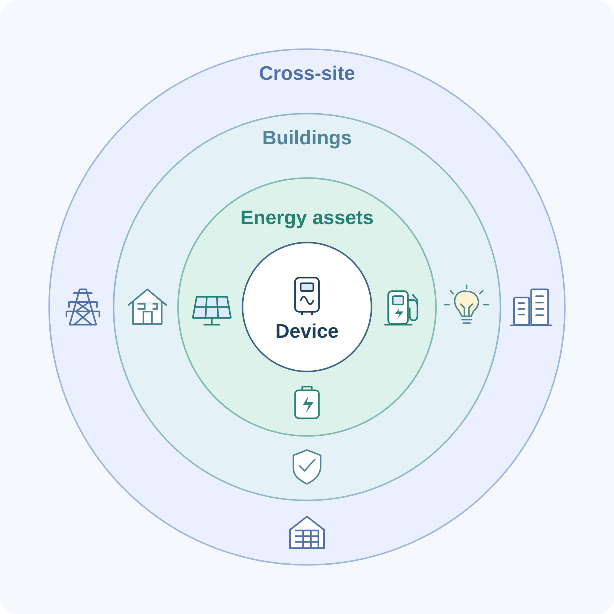
From the center outward: an individual device, coordinated energy assets, buildings and homes, and cooperation with the grid and other sites. Icons illustrate possible participants, rather than standardized product tiers. Actual scope depends on accessible information, interfaces and management authority.[6][8]
Overall coordination and local control
As management scope expands, overall coordination and local control need clearly assigned responsibilities. The University of California, Irvine’s 2016 generic microgrid controller specification distinguishes a master controller from controllers for generation, loads, storage and other equipment. The master controller uses equipment states and dispatch rules to calculate commands, coordinating equipment through start/stop requests, operating modes and setpoints. Equipment controllers continue to provide local control.[6]
The levels here describe the scope of decisions and the responsibilities assigned to each level. A higher level establishes requirements shared by several participants and passes executable instructions to lower levels. Each lower level handles the corresponding actions within its own capabilities and operating limits. Overall coordination needs information about available capability, current state and relevant constraints; the details of internal equipment control can remain local.
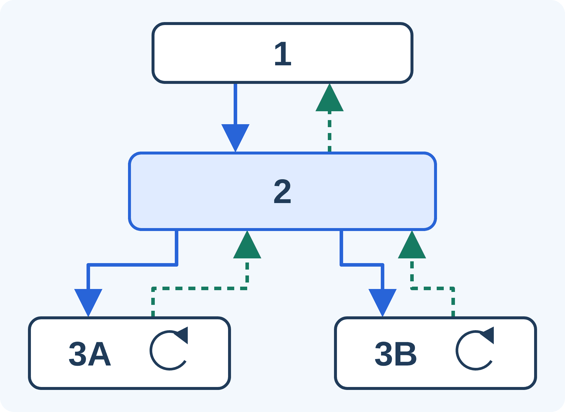
1: higher-level coordination or an external source of requirements; 2: coordination at this level; 3A and 3B: local equipment control.
Solid blue arrows carry objectives, constraints and operating requirements downward. Dashed teal arrows return state, available capability and results. Circular arrows inside the equipment boxes represent local control remaining in operation.
The diagram shows responsibilities, without prescribing the number of controllers or their physical location.[6]
A supervisory computer can provide monitoring, calculation and coordination for the overall system while local equipment controllers continue to handle their own operation. Understanding how much management work the supervisory computer performs means examining the information it receives, the decisions assigned to it and how it works with local control.
These functions can also be distributed across equipment and software. The microgrid specification separates functions from physical implementation and allows centralized or distributed arrangements. The division of management responsibilities and the number or location of computers are distinct design decisions.[6]
Updating plans as conditions change
Shared rules still need to be applied as conditions change. Equipment states, energy demand and available resources vary, so management needs feedback to determine whether a plan remains suitable. Information can also arrive from outside its scope, including grid operating requirements, prices and requests from other systems.[6][7]
Rules can take the form of a decision method that runs repeatedly: objectives, constraints and updated data are used to calculate power allocations, setpoints or task sequences. A change in input produces a new plan while the underlying rules can remain unchanged. Changing priorities, the permitted scope of adjustment or the decision logic involves changing the rules themselves. Algorithms turn this basis for decisions into specific operating plans.
The microgrid specification distinguishes these two kinds of work. Dispatch rules can be set in advance by an operator or modified in real time by an optional optimization function. The master controller then uses the rules and equipment states to calculate dispatch commands. Design and configuration determine how far the system may calculate autonomously and which decision rules it may change.[6]
A system may itself operate under another level of management. In the specification’s proposed ancillary-service functionality, the microgrid controller receives dispatch signals from the grid operator and updates its internal dispatch rules. Local equipment can receive operating modes or setpoints without processing all the external information individually. Translating external requirements into executable internal instructions is part of the work assigned to this level.[6]
Dynamic power management for charging illustrates how repeated calculation affects equipment operation. Tesla’s relevant functionality adjusts charging current according to other household consumption and available site capacity. Its group power management coordinates several charging units within shared capacity. Overall limits can be set in advance while the actual allocation changes with consumption.[9]
More detailed decisions can also account for later consequences. A 2019 virtual power plant study used model predictive control, validated in hardware-in-the-loop simulation, to schedule aggregated resources while considering their energy states and constraints. It addressed a problem with flexibility: capability available now may be exhausted through sustained use, so the use of limited resources must be considered over a period of time.[10] Calculation thus extends from responding to the present state to finding feasible plans for subsequent periods.
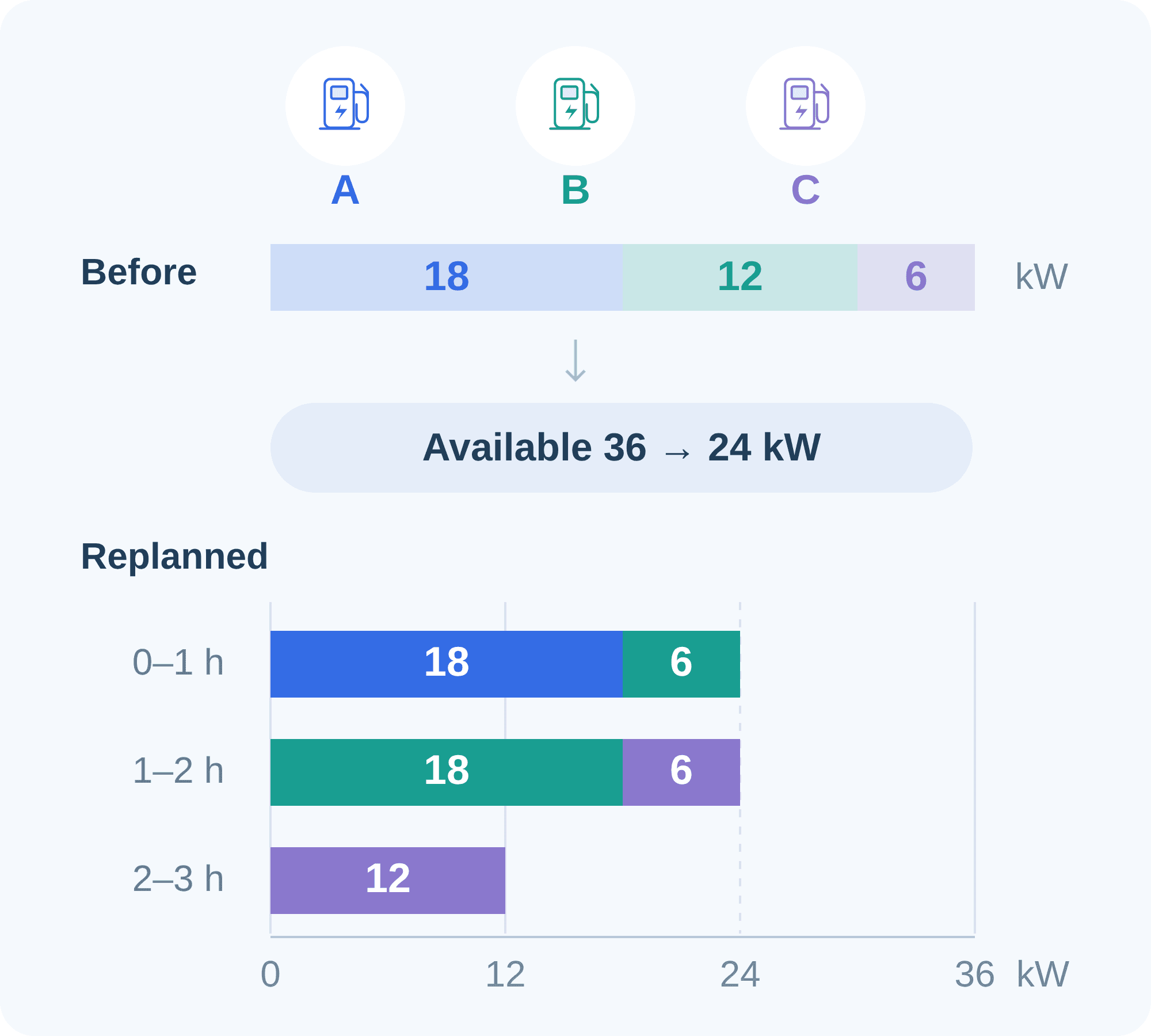
Blue, teal and purple identify A, B and C. Bar lengths and numbers show power; an absent color means zero. The vehicles need 18, 24 and 18 kWh and leave after 1, 2 and 3 hours, respectively. The site limit is 60 kW and each charger is limited to 22 kW. Other consumption rises from 24 to 36 kW, reducing the capacity available for charging.
Time zero is the point of replanning, before any of the required energy has been delivered. The chart shows one feasible plan if 24 kW remains available. It ignores losses and charging curves and assumes vehicles follow the power setpoints. New data calls for recalculation; this is neither a particular product’s algorithm nor a claim of optimality.
Broader scope and deeper decisions
These responsibilities provide a way to understand an energy management system (EMS): a system that, within a defined scope of energy operation, supports the establishment, implementation and adjustment of operating rules so that energy production, storage and use meet specified objectives and constraints. This is a synthesis of the management processes described above. The responsibilities a particular system performs depend on its design and division of work.
Some systems provide information for people to assess and act on. Others execute configured rules; some also calculate plans or update dispatch rules within their delegated authority. These responsibilities can be supported by embedded equipment functions, a dedicated site controller, local software or a cloud service. Monitoring, communication, analysis and control support different parts of the process.[6][7]
The preceding examples suggest two ways energy management capability can develop. One is to broaden the scope of coordination, considering more devices, systems and user requirements together. The other is to deepen decision-making capability, using continually updated data to form more detailed plans that also account for future consequences, within defined objectives and constraints. The first changes what is managed together; the second changes how plans are made.
Both can occur at once. A virtual power plant brings distributed resources into coordinated dispatch, expanding the scope of coordination while introducing trade-offs among resource capabilities, energy states and schedules over time.[10] Energy management can therefore extend into cooperation across systems or develop more detailed calculations within an existing scope. The appropriate capability depends on the problem and the actions that can actually be carried out.
From the manually staffed plant room to today’s systems, energy management systems have gradually taken on work that people performed: establishing rules, gathering information and organizing operation. Those responsibilities also help explain their development: enabling previously separate participants to work together and making operating plans responsive to more changes. Hardware, software and platforms provide these capabilities; management scope, decision-making authority and decision methods determine how broadly and deeply the system can act.
References
- [1] Cornell University, Facilities and Campus Services · Energy Management and Control System (EMCS) · University operating history; no overall revision date shown; historical sections.
- [2] T. E. Dy Liacco / IEEE Transactions on Power Apparatus and Systems · The Adaptive Reliability Control System · May 1967, PAS-86(5), pp. 517–531; cited discussion: pp. 517–520.
- [3] National Research Council / National Academies Press · The Role of Public Agencies in Fostering New Technology and Innovation in Building — Appendix E · 1992; p. 93, “Energy Management in Buildings.”
- [4] Cheol Park / National Bureau of Standards · Demand Limiting Algorithms for Energy Management and Control Systems · February 1984, NBSIR 84-2826; printed p. 1 and the demand-limiting sections.
- [5] Pacific Northwest National Laboratory / U.S. Department of Energy · Energy Management and Control System: Desired Capabilities and Functionality · April 2005, PNNL-15074; printed pp. 3–8 and 17–18.
- [6] G. Razeghi, R. Neal and S. Samuelsen / University of California, Irvine; DOE-funded project · Generic Microgrid Controller Specifications · October 1, 2016; printed pp. 9–13, 15–18, 24–31 and 36; functions, control levels, dispatch rules and communication.
- [7] Australian Government / YourHome · Smart homes and energy management · Updated 2026; month and day not specified; sections including “Home Energy Management Systems” and “Hot water control.”
- [8] ASHRAE SSPC 135 / BACnet Committee · Frequently Asked Questions · No overall revision date shown; supported building systems, interoperability and configuration; checked October 30, 2026.
- [9] Tesla Support United Kingdom · Wall Connector Power Management · No overall revision date shown; “Dynamic Power Management” and “Group Power Management”; checked October 30, 2026.
- [10] M. Amini, A. Khurram, A. Klem, M. Almassalkhi, P. D. H. Hines / University of Vermont · A Model-Predictive Control Method for Coordinating Virtual Power Plants and Packetized Resources, with Hardware-in-the-Loop Validation · January 12, 2019, arXiv:1901.03773v1; abstract and Sections IV–VI; hardware-in-the-loop simulation study.