
Contents
Getting data from field devicesAddressing the data to read or writeBringing field communication onto TCP/IP networksSecuring communication over the networkTurning returned values into device informationGiving devices a shared data modelConnecting equipment to energy management
Getting data from field devices
An energy manager uses a meter to track site power demand and a battery controller to determine how much energy is available. Those inputs help it schedule charging and discharging. To obtain them, the manager and the devices need an agreed way to initiate a query, identify the requested data and return an answer.
Modicon introduced Modbus in 1979 for serial communication between industrial control devices. It let controllers obtain field status, read measurements and write settings. The communication follows a request-response model: a client initiates a request and a server processes it and responds. When an energy manager reads a meter, the manager acts as the client and the meter as the server.[2][8][1]
Modbus RTU is a transmission mode for serial Modbus that encodes requests and responses as binary messages. A common physical interface is RS-485, which lets several devices share a bus. RS-485 defines the electrical signaling; RTU defines how messages are organized and separated. Together, they provide the communication link in this arrangement.[3]
On the bus, the client sends requests to devices in turn, and each addressed device processes the request and responds. An exchange takes time to transmit, process and await a response. If a request times out, the client may retry according to its configuration. A complete polling cycle therefore depends on the number of devices, message lengths, serial bit rate and device response times.[3]
Addressing the data to read or write
The controller also needs to tell a device which data the request concerns. Modbus organizes access around bits and registers: a bit can represent an on/off state, while a register contains 16 bits of data. The client specifies an operation with a function code and supplies parameters such as an address and quantity. The server returns the requested data or an exception response.[1]
| Object | Size per item | Client access |
|---|---|---|
| Coils | 1 bit | Read and write |
| Discrete inputs | 1 bit | Read only |
| Input registers | 16 bits | Read only |
| Holding registers | 16 bits | Read and write |
A meter can map power and energy values to registers, while an inverter can expose operating states and output parameters. The device interface documentation lists the supported objects, addresses and operations. With that information configured, the manager can use a common set of read and write operations to access different devices.[1]
Bringing field communication onto TCP/IP networks
As factories needed to share field data with more computers and management systems, device communication expanded towards plant and enterprise networks. Ethernet technology matured and implementation costs fell, creating a basis for connecting field systems to corporate intranets and manufacturing execution systems, or MES.[7]
Modbus extended to TCP/IP in this setting. The manager addresses a device by its IP address and connects to its Modbus service on TCP port 502. The security specification records the IANA registration of this port in 1996; an open Modbus TCP/IP specification followed in 1999 to support implementation of this network communication.[4][6][7]
Modbus TCP retained function codes and access to bits and registers, carrying forward the read, write and response model. The surrounding message format adapted to the transport. RTU uses a serial address, error checking and silent intervals between frames. Modbus TCP places a header before the function code and data, using a transaction identifier to match requests with responses and length information to identify message boundaries, then carries the messages over TCP/IP.[3][4]
Existing serial devices can join this network through a gateway. The manager sends a Modbus TCP request to the gateway, which initiates the corresponding exchange with a downstream serial device. This lets an Ethernet-based supervisory system work with existing field devices and wiring.[4]
For a group of devices served by one controller, a serial link can continue to support field communication when it meets the required update cycle. Connecting that group to a supervisory network then becomes a choice between a gateway and direct TCP interfaces, based on device interfaces, access requirements and the conditions for modifying the installation.
A read request sent through a gateway travels through both the TCP/IP link and the downstream serial exchange. The manager waits for that exchange to complete before receiving the result. Serial transmission, device processing and response waiting therefore remain part of the collection cycle when the installation retains serial devices.[4][3]
Securing communication over the network
Once devices are connected to a network, a manager can issue read and write requests over that network. A device processing a request to change a setting needs to establish which manager sent the request and which operations that manager may perform. The communicating parties also need to protect the confidentiality and integrity of the data in transit. These requirements bring identity, transport protection and operating permissions into the Modbus interface.[6]
The security extension addresses these requirements through a TLS-based service. IANA registered the secure service mbap-s on port 802 on June 10, 2014. On October 29, 2018, the Modbus Organization formally announced the publication of Modbus Security. Traditional Modbus TCP uses port 502; the security service accepts connections on port 802.[10][9]
The manager and device first complete a TLS handshake, validate each other’s certificates and establish a protected session. They then exchange the existing Modbus TCP messages within that session. TLS provides encryption and integrity protection. With role-based authorization configured, the server uses role information carried in the client certificate to check requests against rules defined by the device vendor or customer.[6]
Using the security service requires protocol support at both ends, together with certificates, trust settings and authorization rules. Once configured, the original register operations can take place within the protected session and the agreed access permissions.[6]
Turning returned values into device information
Across serial links, TCP/IP and protected sessions, reading and writing device bits and registers remains central to the communication. After obtaining the data, the manager uses device documentation to interpret it as measurements or operating states. Reading a meter’s active power provides a concrete example.[1][4][6]
Suppose a meter exposes active power in one holding register. Its documentation specifies a message address of 100, counted from zero, and a scale of 0.1 W per integer count. The client uses function code 03 to read one register at that address. A returned value of 1250 then represents 125 W. The address, scale and values in this example are hypothetical.
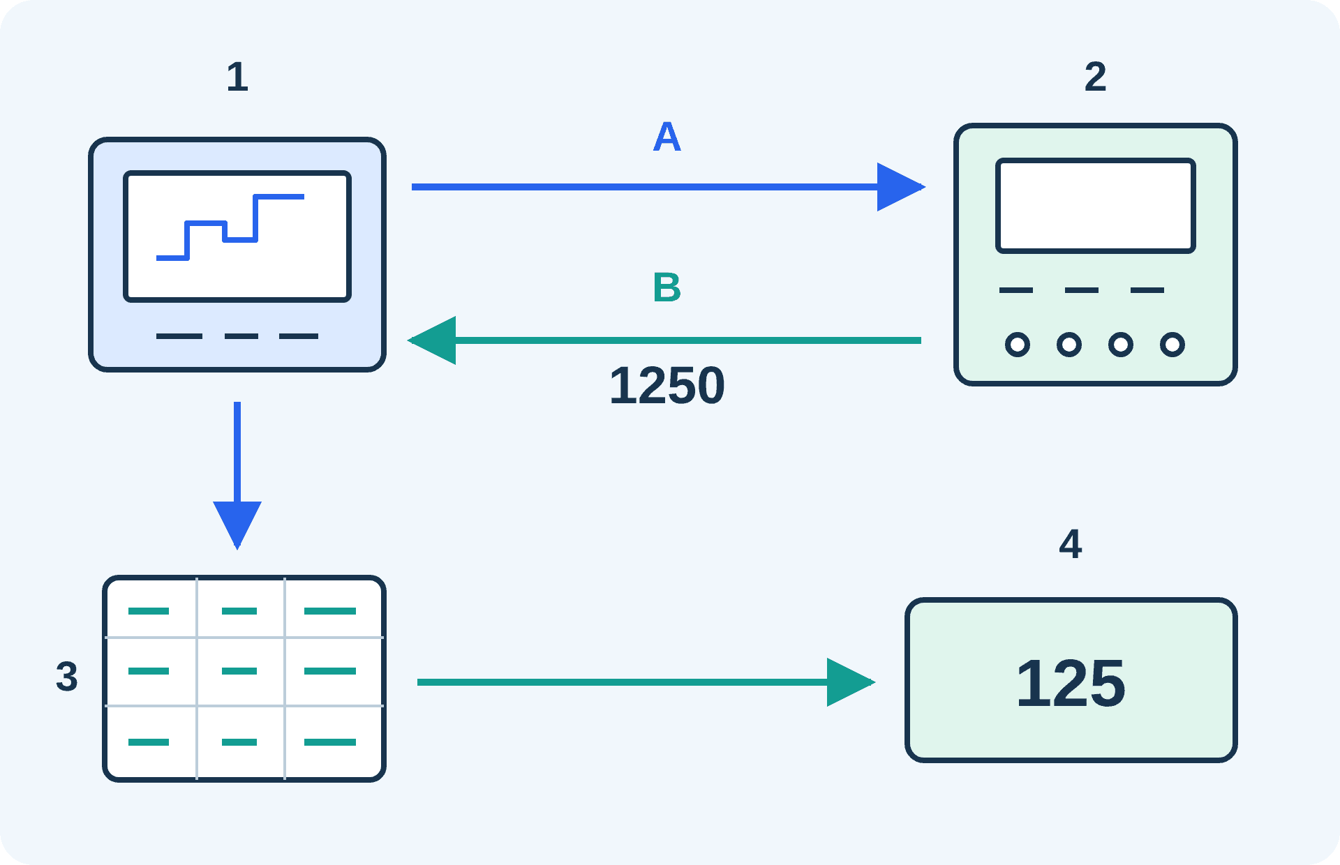
Author-drawn teaching example based on the request-response and register mechanisms in [1]. The address and scaling follow the hypothetical example above. Item 3 is device register documentation consulted by the integrator.
The conversion from 1250 to 125 W depends on the documented physical quantity and scale. A device register map typically records this mapping, identifying the quantity, unit, data type and scaling at each address, as well as the permitted read and write operations. The Modbus application specification leaves the mapping between registers and device application data to the particular vendor and device.[1]
Longer values also require several registers to be combined. A 32-bit value occupies two 16-bit registers. The protocol specifies that the high byte within each register is transmitted first; the arrangement of a value across registers needs to be checked against the device documentation. The manager combines them in the specified order to reconstruct the value.[1][2]
Giving devices a shared data model
Configuring register maps device by device creates repeated work: interpreting the same physical quantities across different equipment. The energy industry can add common definitions for those quantities. SunSpec Device Information Models define data points, types, units, scale factors and access attributes for distributed energy equipment, together with their mapping to Modbus registers.[5]
Devices implementing the relevant SunSpec models share a basis for interpreting their data. Integrators configure monitoring and control around the models and points each device actually implements. Modbus supplies the read and write mechanism, while SunSpec defines the meaning and structure of the data accessed through it.[5]
Connecting equipment to energy management
From RTU to TCP/IP and the security service, Modbus has adapted the same device-access mechanism to wider networks and additional security requirements. Controllers continue to work with bits, registers and function codes, supported by arrangements for transport, access protection and data interpretation.[1][3][4][6]
To schedule battery charging and discharging from site demand and battery state, an integrator needs to establish the communication path, access permissions, data meanings and available control functions for the equipment. Those configurations allow information and operations distributed across meters and battery controllers to contribute to the same energy management process.
References
- [1] Modbus Organization · MODBUS Application Protocol Specification · V1.1b3, April 26, 2012; sections 1, 4.1–4.4 and 6.3
- [2] Modbus Organization · An Introduction to Modbus · Official introduction; history, data mapping and “Floating-point values in Modbus”; checked October 22, 2026
- [3] Modbus Organization · MODBUS over Serial Line Specification and Implementation Guide · V1.02, December 20, 2006; sections 1.2, 2.1, 2.4, 2.5 and 3
- [4] Modbus Organization · MODBUS Messaging on TCP/IP Implementation Guide · V1.0b, October 24, 2006; sections 3.1 and 4.2
- [5] SunSpec Alliance · SunSpec Device Information Model Specification · Version 1.2, July 8, 2024; sections 3, 4.2 and 6
- [6] Modbus Organization · MODBUS/TCP Security Protocol Specification · Document identifier MB-TCP-Security-v36_2021-07-30; sections 5–6 and 8
- [7] Modbus Organization · Modbus FAQ · Official FAQ; Modbus origins, the open TCP/IP specification and network-integration context; checked October 22, 2026
- [8] NI · Application Development with Modbus · Updated May 30, 2025; Overview: 1979 origins and initial serial transport
- [9] Modbus Organization · Modbus Security: New Protocol to Improve Control System Security · Official publication announcement, October 29, 2018; TLS, certificates, roles and ports 502/802
- [10] IANA · Service Name and Transport Protocol Port Number Registry · mbap (502/tcp) and mbap-s (802/tcp); port 802 registration date June 10, 2014; checked October 22, 2026