Contents
The need for shared device dataFrom specifications to interoperability testingInverters take on grid functionsOrganizing devices through information modelsDiscovering models and reading dataPutting control settings into effectSecurity and device integration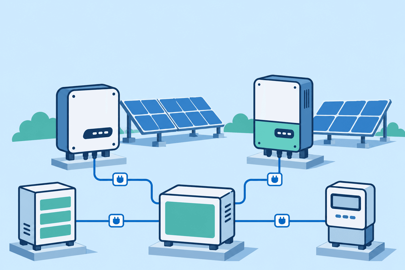
Managing a solar installation involves bringing together data from inverters, meters and other equipment. When these devices come from different manufacturers, integrators have to connect their power readings, voltages and operating states to a shared set of monitoring and control functions. SunSpec began by standardizing how devices express their data, then extended that shared interface to support the grid functions of smart inverters.
The need for shared device data
On July 15, 2009, the SunSpec Alliance announced its formation at Intersolar North America. Its founding members included inverter manufacturers such as SMA, Fronius and KACO, alongside companies involved in monitoring, instrumentation, networking and project investment. The announcement identified open data standards and monitoring and management interfaces as priorities. Its first project was the SunSpec Modbus specification.[2]
Once equipment was operating, owners needed to track generation, monitoring providers needed continuing access to operating data, and integrators needed to connect components from different suppliers. In the founding announcement, Fat Spaniel's Tom Tansy cited demand from owners, financiers and integrators for open interfaces as a reason for supporting the alliance.[2]
Modbus was already used for device communications. It lets a management system read or write registers: numbered locations that hold values in a device. Manufacturers defined the meaning, units and encoding of those registers. A later EPRI assessment identified the repeated engineering work required by these custom register maps as a direct reason for SunSpec's development.[3]
Suppose two inverters provide AC power readings over Modbus. One stores an integer in watts; the other stores a value reduced by a scale factor. An integrator has to consult both manuals and implement the appropriate reading and conversion rules for each. SunSpec establishes common definitions for the meaning, placement and conversion of these values.
From specifications to interoperability testing
On May 11, 2010, the alliance released its first proposed communications specifications for public comment. It called for a shared data language across manufacturers and explicitly aimed to make use of existing standards.[4] SunSpec built on Modbus communications by defining how device data would be organized and interpreted.
In June that year, the alliance announced plans for its first PlugFest interoperability event. The specifications already covered data formats for inverters, meters and environmental sensors. The event was intended to bring device manufacturers and information system developers together to check how data could be provided, located and used according to the shared rules.[5]
Inverters take on grid functions
SunSpec's work expanded into inverter control. In April 2012, the alliance opened its Advanced Inverter Control specification for its first public review, extending the common rules for accepting control settings.[6]
In early 2013, the California Public Utilities Commission (CPUC) and California Energy Commission (CEC) established the Smart Inverter Working Group to explore how advanced inverter functions could help manage the effects of large amounts of DER on the grid. The work addressed autonomous functions, communications protocols and further advanced functions in successive phases.[7]
Smart inverters can adjust output in response to local voltage or frequency conditions and accept settings through a communications interface. Management systems need to understand their capabilities, configure operating parameters and read the resulting feedback. The device interface expanded from reporting generation to expressing adjustment capabilities and accepting control settings.[7][8]
IEEE 1547-2018 incorporated interoperability requirements into the DER interconnection standard. It requires the local DER communications interface to support at least one of three specified protocols: SunSpec Modbus, IEEE 2030.5 or IEEE 1815 (DNP3). Decisions about external communications networks and protocol use are left to the relevant interconnection authorities and grid operators.[8]
SunSpec's implementation guide for IEEE 1547-2018 uses information models 701–713 to cover measurements, capabilities, entering service, power controls and responses to voltage and frequency. These models map interconnection requirements to defined data and settings in the device interface.[9]
For communications between the relevant utilities and DER, California Rule 21 uses IEEE 2030.5 by default, with implementation requirements set out in the Common Smart Inverter Profile (CSIP). A site using this arrangement can connect its internal equipment through SunSpec Modbus, with a controller or gateway handling the external communications. The topology and protocol choices are configured for the project's requirements.[1]
Organizing devices through information models
An information model groups related data points and defines their names, meanings, types, units, access rights and implementation requirements. Each model receives a standard model ID.[10]
Manufacturer and product names describe identity. Voltage and power readings describe operation. Power limits belong to control. These groups form models that a device combines according to its capabilities; management software uses the corresponding definitions to identify and interpret the data.[10][11]
The model library includes several main groups:[11][16]
| Purpose | Model or series | Main content |
|---|---|---|
| Common identity | Model 1 | Manufacturer, product model, serial number and other information identifying the device. |
| Inverters | 100 series | Operating measurements and associated controls. Model 103 covers three-phase inverter monitoring; model 123 provides immediate controls. |
| Meters | 200 series | Voltage, current, power, energy and other metering information. |
| Environment and auxiliary PV equipment | 300–600 series | Environmental measurements, string combiners, PV modules and trackers, respectively. |
| DER grid functions | 700 series | Measurements, capabilities, entering service and grid support controls for the corresponding IEEE 1547 device interface. |
| Storage and batteries | 800 series | Battery capabilities and state, including information at bank, string and module levels. |
| Vendor extensions | Vendor-defined models | Additional functions described by the relevant extension definitions. |
Inverter and meter models are organized around types of equipment. The 700 series concentrates on the capabilities and functions a DER provides at its grid connection. For example, model 701 covers AC measurements, 702 describes capabilities, and 704 provides AC controls. Storage equipment can expose these grid functions alongside information specific to its batteries.[9][11][12]
A device combines several models to describe its identity, operating state and available functions. A three-phase inverter can use the common model for identity, model 103 for operating measurements, and other applicable models for its control functions. The combination depends on the device and its implementation requirements. Management software obtains this list through model discovery.[10][11]
Discovering models and reading data
The management system establishes Modbus communications with the target device using its configured network or serial connection parameters. It then locates the SunSpec models within the device's register map.[10]
A SunSpec map begins with the SunS marker, followed by a continuous sequence of models. Each model starts with its ID and a length value, L, followed by its data. Acting as the client, the management system uses the ID to select the model definition and the length to determine the extent of the data block.[10]
Discovery follows this sequence:[10]
- Find the starting point. The client checks the candidate starting locations specified by SunSpec. Finding the SunS marker establishes where the map begins.
- Read the model header. The ID and L immediately following the marker identify the first model and the number of registers occupied by its data.
- Use the length to locate the next model. The client advances past the current data block to the next header, recording model IDs and locations as it proceeds.
- Stop at the end model. A model with hexadecimal ID FFFF and length zero marks the end of the map.
The ID identifies the model; the length locates the next one. Together they let the client build a list of the models the device actually provides. Using the model definitions it already has, the client can then determine where each data point is located, read its current value and interpret it.[10][11]
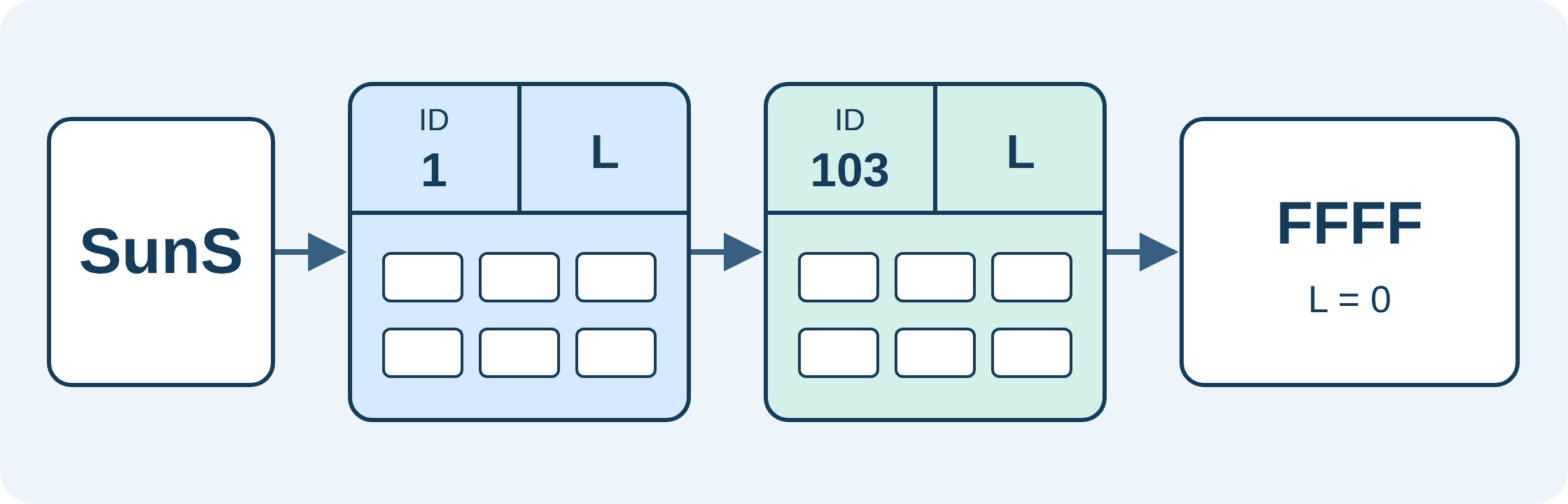
SunS marks the start of the map. Model 1 supplies identity information such as manufacturer and product model. Model 103 supplies three-phase inverter monitoring data. FFFF is the hexadecimal end-model ID. ID identifies the model type, L specifies the number of data registers that follow, and the arrows show the order in which the client locates the models.
The blocks illustrate the sequence; L gives each model's data length. Devices combine models according to their functions and implementation requirements.
The length also lets a client pass over an unknown model and continue to later models. When a device adds another standard model or a vendor extension, the client can continue using the parts it recognizes. Management software can use the new content once it has the corresponding definition and the ability to handle it.[10]
Devices mark unsupported optional points with the unimplemented value defined for that data type. Control functions use enable states and execution rules to determine which operations are available.[10][12] The management system uses the model list, valid data and function states to establish the monitoring and control functions it can use.
Putting control settings into effect
Control models describe settings, enable states and execution feedback, allowing the management system to follow a setting from its transmission to its adoption.[12]
For example, model 704 describes a maximum active power limit and its enable state separately. The management system sets the limit to 90% of the nameplate active power rating and enables the corresponding function. The device then limits active power to that ceiling.[12] The setting and the enable state jointly determine whether the control function is in effect.
For functions that use curves, the management system submits new settings and the device reports the adoption result. After successful adoption, the current curve read back from the device reflects the new settings. Some functions also support a reversion timer. With the timing mechanism enabled, updating the settings restarts the timer; expiry restores a specified alternative set of settings.[12]
SunSpec has continued to refine testing requirements for these operations. Its 2024 specification update addressed interoperability problems involving function-code support, interpretation of enable fields and read/write timing, adding or clarifying the associated requirements and tests.[13]
Security and device integration
Remote control also involves connection identities and operating permissions. In October 2026, SunSpec announced approval of the Secure SunSpec Modbus Test Procedures. The associated certification pathway covers authentication, encrypted communications and role-based access control.[14]
Equipment selection and integration require checking the device's implementation. Before integration, confirm the models, valid data and controls it provides, together with its communications and security configuration and the scope of its certification. SunSpec's product registry lists products by certification type and can be used to check the corresponding certification information.[15]
Starting with monitoring interfaces for solar equipment, SunSpec progressively brought data meanings, model discovery and control behavior into shared specifications. These reusable, testable agreements provide an interface foundation for equipment from different manufacturers to work together. Devices expose models according to their capabilities, and management systems use those models to organize monitoring and control.
References
- [1] SunSpec Alliance, Specifications, specification directory, accessed November 15, 2026.
- [2] SunSpec Alliance, SunSpec Alliance to Advance Renewable Energy Standards, July 15, 2009.
- [3] EPRI, Evaluation of SunSpec Modbus for Distributed Energy Resources: Results from EPRI Interoperability Testing and Market Research, Technical Update 3002009854, December 2017, Chapter 3.
- [4] SunSpec Alliance, Releases Draft of the First Specification for Renewable Energy Standards for Public Comment, May 11, 2010.
- [5] SunSpec Alliance, Announces First Annual Plug Fest Solar Interoperability Event, June 23, 2010.
- [6] SunSpec Alliance, SunSpec Releases 2012 Specification Update, April 4, 2012.
- [7] CPUC, Smart Inverter Working Group, history and phased work, accessed November 15, 2026.
- [8] NREL, A Guide to Updating Interconnection Rules and Incorporating IEEE Standard 1547, NREL/TP-5D00-75290, October 2021, p. 38.
- [9] SunSpec Alliance, SunSpec Modbus IEEE 1547-2018 Profile Specification and Implementation Guide, v1.1, Sections 2–3.
- [10] SunSpec Alliance, SunSpec Device Information Model Specification, v1.2, July 8, 2024, Sections 3, 4 and 6.
- [11] SunSpec Alliance, SunSpec Model Definitions, v2026-04-20, common, equipment and DER model definitions.
- [12] SunSpec Alliance, SunSpec DER Information Model Specification, v1.2, Section 3 and the DERCtlAC model.
- [13] SunSpec Alliance, Modbus Specification Updates, October 29, 2024.
- [14] SunSpec Alliance, Press Release: Secure SunSpec Modbus Certification, October 21, 2026; test procedures approved October 7, 2026.
- [15] SunSpec Alliance, Product Certification Registry, accessed November 15, 2026.
- [16] SunSpec Alliance, SunSpec SVP Dashboard Data Sheet, 2021, p. 2, model-series classification.